Atlas Drift Crane
Introduction to Mechanical Engineering Final Project Report
Team Atlas Drift (Team 302-1) — Raul Gupta, Derek Zhang, Sean O’Grady, Cameron Gabbey
I. Introduction
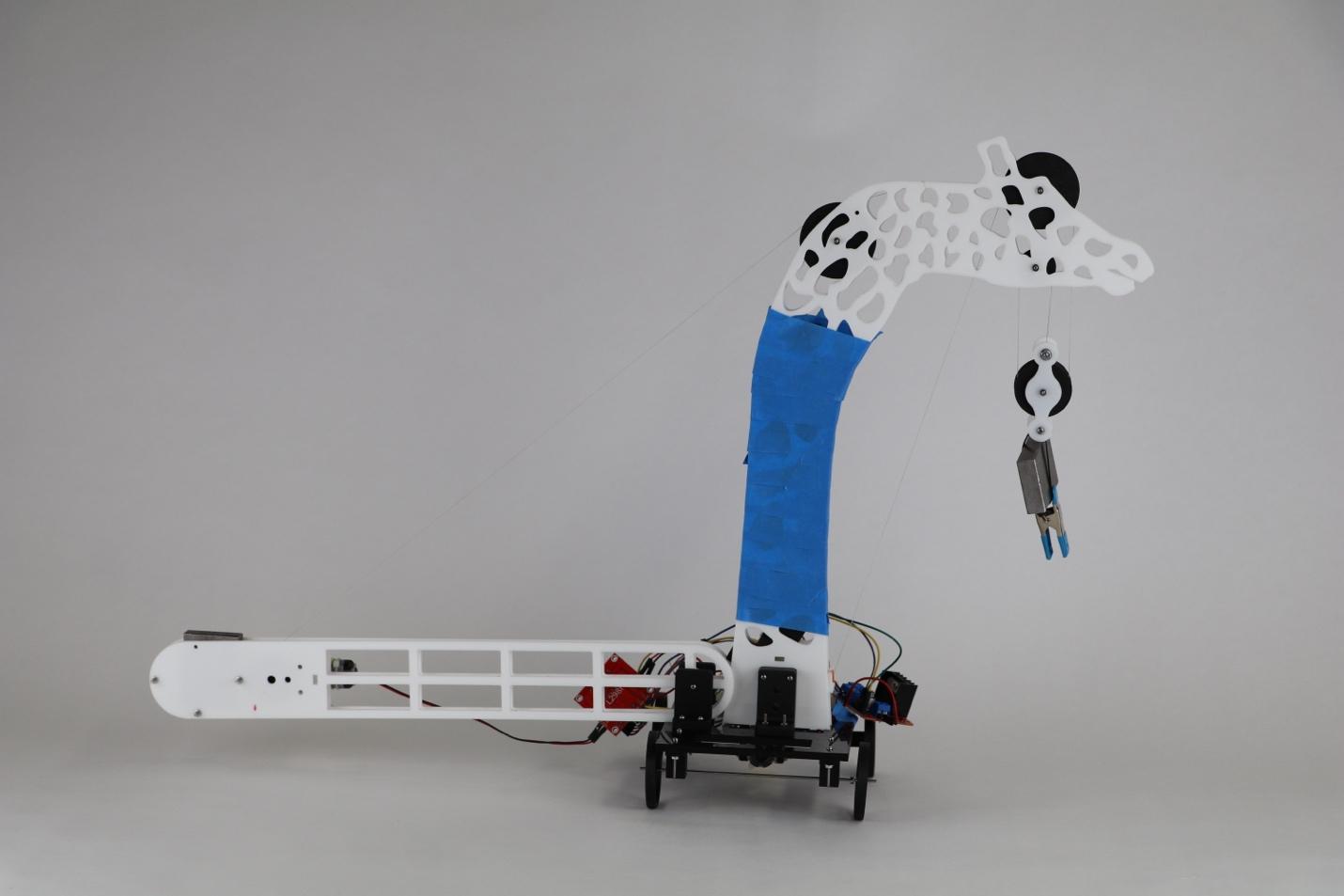
The goal for this project was to create a crane within the project’s regulations that could easily lift the weight of 1.75kg at a speed well above the 0.0300 m/s standard over a 30” lift and travel 2 feet with the weight suspended. To achieve this, Atlas Drift used a dynamic counterweight which swung on an arm to its extended position and a block and tackle system with a mechanical advantage of three to lift the weight. An Arduino was used to control the crane via two joysticks. One joystick operated the drive motor while the other controlled the lift motor and dynamic counterweight on separate axis.
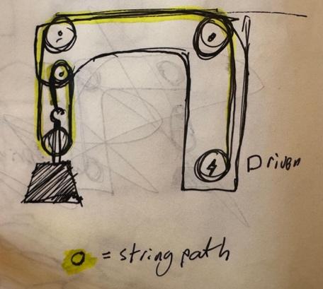
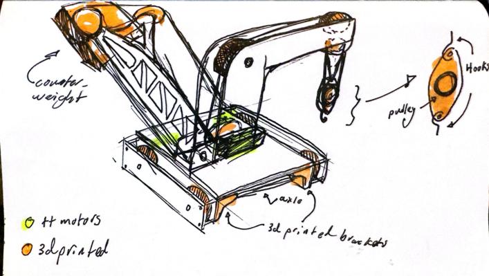
Figure 1: (Left) An early design for the block and tackle system. (Right) Early sketch of the overall crane including the pulley block.
II. Design
The design process for each subsystem is explained below. Subsections are ordered chronologically based on which was designed first.
II.A Lift System
The first optimized aspect of the crane was the lift speed. A mechanical advantage was needed since the motor stalls at a load of 1.75 kg. The stall torque in Figure 2 came from about 1.1 kg with a radius similar to what will be present in the crane.
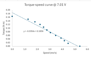
Figure 2: Torque-Speed graph of the TT motor.
The block and tackle system was chosen over gears due to the latter’s disadvantage of needing precise meshing to function properly. For the fastest lift speed, a mechanical advantage of five was necessary (see Figure 3), but an advantage of three was chosen due to the added complexity of higher values. The initial design began with the sketch depicted in Figure 3, but it was too large since it impacted the load’s ability to clear the table. Its mass could also be shaved off by reducing overall footprint. The final version resolved these issues, and Figure 3 shows the model of the block and tackle system used in the competition.
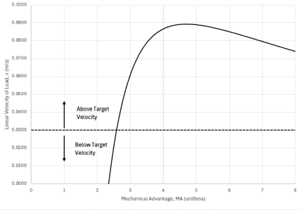
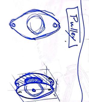
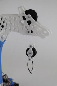
Figure 3: (Left) A graph of lift velocity by mechanical advantage. (Middle) Early sketch of the block and tackle system. (Right) Final block and tackle system.
After establishing the lifting mechanism, the shape of the boom was developed. Several factors affecting the boom were structural integrity, mass, fabrication, regulations, and appearance. It needed to house pulleys for the block and tackle system, so a two-paneled boom was chosen with the pulleys sandwiched between. Splines were used for the general shape of the boom so that it would have a smoother look, and the boom was dimensioned so that the chassis would remain under 18” and so that the load would not hit the table. Slots were also cut out from the boom that left behind 0.3” wide bars; this dimension was chosen so that each of the holes for the pulley axles, which were 0.096” in diameter, would have at least a diameter’s worth of acrylic around it. Figure 4 depicts the initial sketch of this structure and provides the first subassembly CAD.
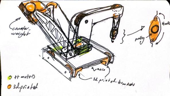
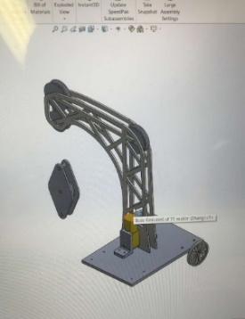
Figure 4: (Left) An initial sketch of the boom, and (right) the initial CAD of the boom subassembly.
This provided enough structural strength for each layer to be made from 1/8” acrylic, minimizing mass. Figure 5 shows a successful FEA of the initial boom.
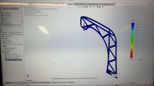
Figure 5: An FEA of one boom panel bearing the full 1.75 kg load. The FoS result is shown, with the minimum and chart scale displayed.
Later, a second version of the boom had to be made due to not accounting for lift height (i.e., the load clearing the table) originally. In addition, real-life testing showed that the load exerted too heavy of a moment around the tipping wheel. This made the counterweight need to be unnecessarily heavy, causing challenges with the mass regulation. Thus, the boom was redesigned to hold the load closer to the crane and to be taller (while remaining under 18”). Figure 6 shows the redesign, which was drawn from natural inspirations, along with the FEA ran on that model.
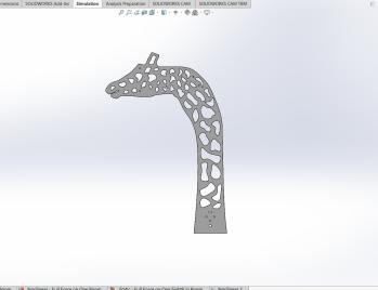
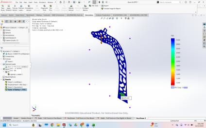
Figure 6: (Left) CAD and (right) FEA analysis of the final boom.
The lift speed was predicted to be 0.06 m/s, and the boom was expected to easily hold 1.75 kg. However, two unexpected results were that the load caused the boom to bend towards the side and that the string did not spool properly. This former was fixed by adding old brackets repurposed as spacers in between the two panels with tape around it to maintain tension. The latter required something to guide the string, and repurposed clip was used with the help of tape (to preserve string lifespan) and superglue. Figure 7 provides visuals of the fixes.
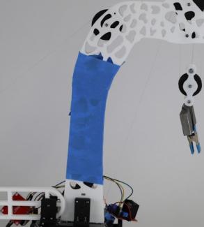
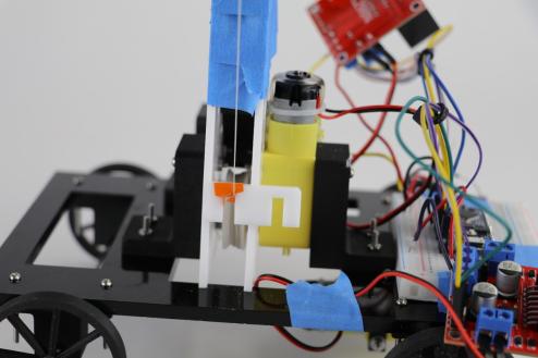
Figure 7: (Left) The boom section with spacers and tape. (Right) A close-up shot of the clip guiding the string.
II.B Chassis & Drive Train
The chassis was constructed under the assumption that the acrylic would easily be able to support the weight of all the components: the boom, counterweight arm, and electronics. A simple initial design was created to map out where all the mounting holes would be. The mounting holes for the boom were centered horizontally, placed slightly lower vertically in anticipation of the counterweight arm. Holes were also added for brackets that would support the wheels and for brackets supporting the wheel motor. Soon after, holes for mounting the counterweight arm were added; the position for these were chosen so that the arm did not collide with the boom during rotation and so that the centers of the arm and boom would line up. From here, mass was optimized by cutting away acrylic around the mounting holes. A space of at least 0.5” was left around each hole as to not compromise structural strength. Figure 8 shows a before and after of the mass optimization.
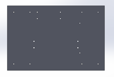
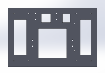
Figure 8: (Left) An overhead view of the initial chassis CAD. (Right) An overhead view of the mass-optimized chassis CAD.
For the drive train, only one pair of wheels is driven by a motor. This reduces overall complexity compared to a four-wheel drive and saves mass. The free-spinning wheels are connected by a 2 mm rod, held in place via brackets. To reduce friction, the brackets were designed to have counterbores that bearings could be pressed fit into. The motor-driven wheels were designed to have their own axles (via 3D-printing) that had slots in them to fit onto the motor shaft. The axles have a diameter of 0.44”, doubled from 0.22”, the diameter of the motor shaft. This left about a radius of material around the slot for stability. Brackets were still used to hold the wheels, but due to the size, a 0.5 mm tolerance, rather than bearings, was used to control friction. Three layers of painter’s tape were added on the inner side of the axles to prevent them from slipping out sideways. Figure 9 provides CAD and real-life pictures of the drive train.
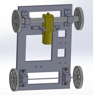
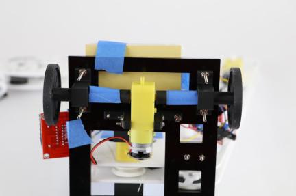
Figure 9: (Left) The underside of the crane CAD. (Right) The underside of the crane, zoomed in on the drive wheels and motor.
The chassis was able to support the weight of the lift and counterweight system as predicted, and it showed strong driving capability after initial code tests.
II.C Counterweight
The stability calculations in Milestone 4, which occurred right before the design of the counterweight, pointed towards a needed mass of just under 300 g (see Figure 10). With the crane sitting around 600 g, it was critical to place the counterweight as far out as possible to reduce the mass.
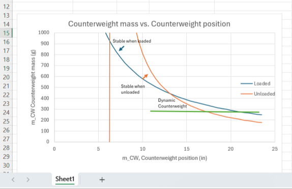
Figure 10: The stability chart from Milestone 4.
The mechanism chosen was a rotating arm driven by a motor at the end where the extra mass sat as well. These components were placed there to maximize their distance, r, from the tipping wheel and moment, M, around that wheel according to Eq. 1.
where m and g are the mass and acceleration due to gravity respectively.
Both ends of the counterweight bar were rounded into semicircles to (1) reduce mass and (2) ensure that the pivot end of the bar did not collide with the chassis. The motor was placed at the other end of the bar so that it could exert a larger torque, τ, with less force, F, making it easier for the motor to lift and lower the arm. Eq. 2 demonstrates this principle. A string was attached from this motor to the top of the boom, going around a pulley. Figure 11 shows this along with a free body diagram of the system.
where r is the radius from the pivot point to the force.
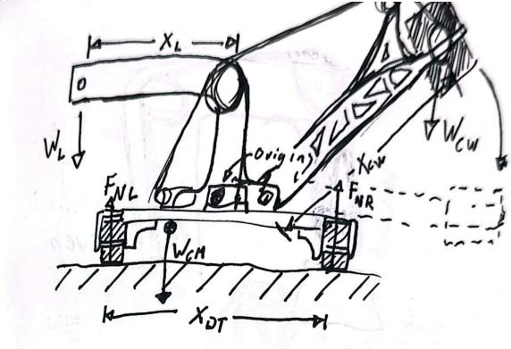
Figure 11: An initial free body diagram sketch of the counterweight system.
The extra mass was placed next to the motor, secured with four bolts placed in a rectangular pattern around the mass. All the space from there to the pivot point was optimized in terms of mass with bars being 0.25” wide instead of 0.3” (see subsection II.A) to reduce mass further. The bolt holes remained 0.096” in diameter, which meant there was still more than a radius worth of acrylic around them. Figure 12 shows the initial design of the counterweight system.
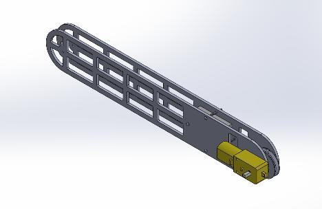
Figure 12: The initial CAD of the counterweight system.
Still, the crane remained dangerously around the mass limit, so the positions of the extra mass and motor were swapped to make the bulk of the mass farther from the tipping wheel. This allows a lighter mass to contribute the same moment around the tipping wheel (see Eq. 1). The motor was tested to ensure there were no issues with lifting and lowering the arm. Figure 13 provides pictures of the final design of the counterweight system.
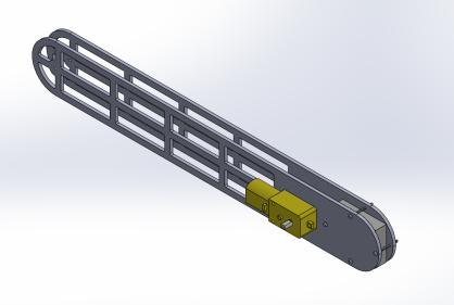
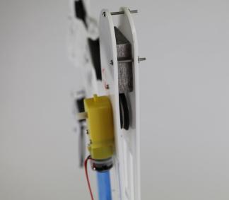
Figure 13: (Left) The final CAD of the counterweight system. (Right) A close-up shot of the end of the arm.
The counterweight arm functioned as expected, lowering and lifting without issue. However, the mass of the crane had to surpass the 900 g limit to lift the full 1.75 kg load, so load capability was sacrificed to stay under the mass limit. The crane was able to lift, transport, and lower a 1041 g load.
III. Ethics of Designs at Scale
This section asks to pick one of the NSPE Rules of Practice that would be most important for design, and why it pertains to the crane. This section also explains how the group could have modified design or design process given the NSPE rules of practice.
The NSPE rule that stands out the most for this design is “Engineers shall hold paramount the safety, health, and welfare of the public.” While the crane was able to successfully lift the load and drive with it, during practices we ran into numerous issues with our string coming off the pulleys. At this small scale, it was no issue to simply put the string back on, but at a larger scale, presumably with big metal cables, that could be very dangerous. Additionally, the string slipping off the pulley would cause the load to jerk and sometimes drop a bit. With a full-size crane, carrying around multiple tons of load, this is a huge health risk. For scaling up this crane, a better guide for our string would need to be designed so it doesn’t slip off. Making pulleys with deeper grooves would also help keep the string from coming off.
IV. Fabrication and Programming
This section provides an overview of how the parts for the crane were created, how the crane was put together, and how the program for the crane’s control system was designed. Also included in the following section is some challenges the crane faced on its way to production.
IV.A Fabrication
The main processes for fabrication were laser cutting acrylic and 3D-printing with PLA plastic. The Boom Assembly, Counterweight arm, and base of the crane were cut from acrylic sheets. The base of the crane was made from ¼” acrylic for rigidity while our boom and counterweight arm were cut from 1/8” acrylic for lightness, instead doubling each so that our pulleys were contained within the booms and counterweight arms. Figure 14 shows this doubled up acrylic.
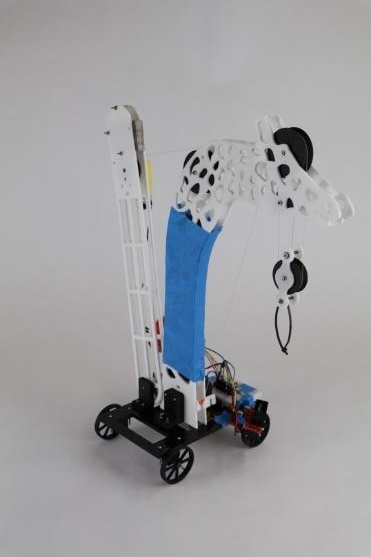
Figure 14: Isometric view of the crane. The counterweight arm utilizes two laser cut pieces of acrylic with the weight block and pulley between the two pieces (left). The boom uses the same thought process containing the pulleys between the two pieces of acrylic (right).
All brackets, wheels, and pulleys were made using the 3D printers in Wendt Commons. This allowed for rapid prototyping and easy adjustment to our parts. For example, the brackets on the underside of the crane went through three major redesigns as the final height of the crane was decided. Additionally using 3D printed parts with precise measurements for bolt holes made the crane very modular making it easy to swap components for updated parts. The only time modifications were made to any parts was to accommodate the motors by boring out existing holes to ensure the motor fit flush to the boom and counterweight arm. Figure 15 shows some of the brackets we 3D printed.
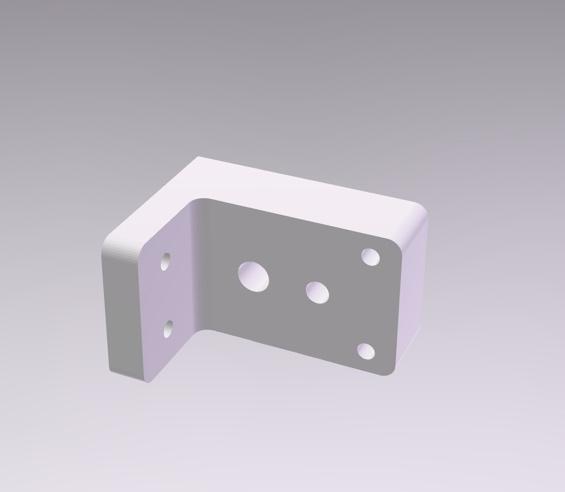
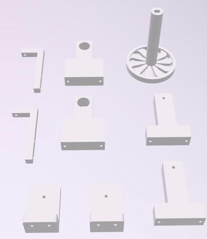
Figure 15: (Left) Boom Bracket which connected the motor, boom, and chassis together. (Right) Layout of one of the iterations of brackets and drive wheels for the drive train.
IV.B Assembly
The assembly was a pretty easy process. It was tricky to have more than one or two people working on the assembly at a given time, because only one or two new parts were added at a time. There were a couple of times when there were bigger changes, like swapping out our old chassis for a new one, which required complete disassembly and reassembly, but even then, there were only one or two people working at a time. Assembling was a lot like Legos, in that the plan for how to put the crane together was already on SolidWorks. Assembly was largely directed by our existing Assembly in SolidWorks, meaning putting the crane together became very straightforward.
IV.C Programming
The code for the team’s crane was relatively straightforward overall. It utilized both provided joysticks, with one being devoted to driving back and forth. To this end, only the y-axis of the first joystick is read by the code. The second joystick was devoted to the movements of the crane lift arm and counterweight system simultaneously. The process of doing this ended up being slightly complicated. Originally, it was designed to make use of the joysticks’ built-in switch function, wherein a user can click the joystick down to trigger a function within the code. This functionality was eventually abandoned after the process of coding it ran into many difficulties with strange errors and complicated signals that seemed hardware related. The team instead moved to using the x-axis of the joystick to control the lift arm, while the y-axis of the joystick was tied to the counterweight arm. This ended up being preferable as it allowed for quick alternating between which motors were being controlled, and it was clear which motor was being controlled. Besides that, the rest of the code is simple control of the motors based on a mapped reading of the joystick, which was almost entirely based on the code we made in class to do exactly that.
V. Performance
Shown below are the performance measurements of each design goal (i.e., load lift speed, total vehicle mass, and vehicle stability). Each subsection is organized into three paragraphs: (1) the calculated values, (2) the observed values, and (3) hypotheses for any deviations between the two values.
V.A Lift Speed
A mechanical advantage of three was chosen for lifting the 1.75 kg load. The original calculations linked this mechanical advantage level to a lift speed of about 0.06 m/s.
The actual recorded lift speed for the full load was about 0.0657 m/s. This means there was a percent error of 8.676% in the calculations.
The calculations were done under the assumption of the motor performing at its least optimal (from all the observed trials) to account for friction, energy loss due to heat, etc. These losses were most likely overestimated, causing a slower anticipated lift speed.
V.B Vehicle Mass
The calculated vehicle mass not including the counterweight assembly was 610.66 g with a vehicle COM of 2.15469” from the tipping wheel. Including the counterweight, the mass was 969.06 g.
The actual recorded vehicle mass was 886.16 g, resulting in a percent error of 9.355% in the calculations. The actual vehicle COM was not determined.
The primary reason for the actual mass being lighter is that a lighter counterweight was used since a lighter load was used. The calculated vehicle mass included a counterweight suitable for the full 1.75 kg, but the design pressures emphasized a lighter vehicle mass over full-load-lifting capability. Some inaccuracies also arose from the process used to mass the vehicle: Each subassembly was weighed as a whole instead of weighing individual components. This may have caused double counting for some sections in the COM calculations.
V.C Stability
The boom length was 3.647”, and the counterweight subassembly’s COM sat about 17.2” from the tipping wheel. According to the stability calculations, this results in a counterweight mass of slightly over 300 g to balance a loaded crane.
A mass closer to 400 g was needed in real life when attempting to balance 1.75 kg, so there was a percent error of 25% in the calculations. For ~1041 g, which the crane lifted for the transport test, a 300 g counterweight worked.
Possible reasons that the actual performance required a heavier counterweight (for lifting the full load) are that the vehicle COM and mass were off. The vehicle COM may have been closer to the tipping wheel than reported, and the vehicle mass was lighter than anticipated as said. The inability to obtain accurate numbers for the COM are due to the shape of the boom, whose COM had to be estimated based on geometric simplification.
VI. Expenses
The team’s budget for the overall project was $20. By the end of testing and final assembly the crane’s total expenses was $14.72. Most of those expenses ($10.75) went towards buying extra acrylic in the final week of testing because of a miscalculation resulting in a redesign of the boom and counterweight arm. Otherwise, the rest of the budget was spent on 3D printing brackets and wheels throughout the iterations of the crane. Figure 16 is the expense chart for the crane.
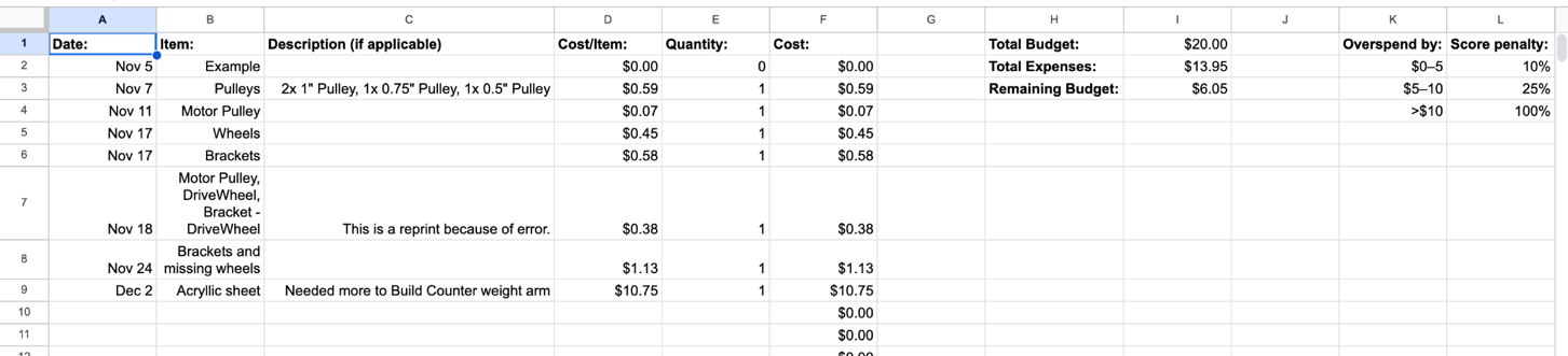
Figure 16: Expense chart visualizing our expenses throughout the project.
VII. My Role
I worked on the original overall design, doing the sketching of the free body diagrams as well as the other sketches (see Figures 1, 3, 4, and 11), to help the team plan and organize our vision. I also made the code for the robot, working with the team on what functions they wanted to implement and how. I worked with Cameron on the wiring of the robot, both planning it and keeping diagrams (see Figure 17), so the rest of the team had references in case the wiring needed fixing.
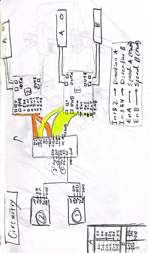
Figure 17: Wiring diagram
I also worked on parts of the CAD, primarily the lift block for the mechanical advantage, as well as the pulleys. Lastly, I worked on the assembly and testing of the crane, serving as the operator during the tests and final challenge, and making some final changes the night before the final test to strengthen the crane enough to complete the task.
VIII. Appendix
int first_x_val;
int first_y_val;
int second_x_val;
int second_y_val;

void setup() {
  Serial.begin(9600); // Set up serial communication

  //*Driver 1
  pinMode(7, OUTPUT); //In1
  pinMode(4, OUTPUT); //In2
  pinMode(3, OUTPUT); //In3
  pinMode(2, OUTPUT); //In4

  pinMode(6, OUTPUT); //EnA
  pinMode(5, OUTPUT); //EnB

  //Driver 2
  pinMode(12, OUTPUT); //In1
  pinMode(11, OUTPUT); //In2

  pinMode(10, OUTPUT); //EnA

  pinMode(9, INPUT);
}
void loop() {
  //Setting up pins to read Joystick input

  //Joystick 1 (Lift up, down)
  first_x_val = analogRead(A7);
  first_y_val = analogRead(A6);

  //Joystick 2 (Move forward, backward)
  second_x_val = analogRead(A5);
  second_y_val = analogRead(A4);

  //Map joystick inputs

  //// Motor Driver 1 ////

  if (first_y_val < 512) {               // if 0 < x_val < 511
    digitalWrite(12, HIGH);              // Motor A backward
    digitalWrite(11, LOW);
    analogWrite(10, map(first_y_val, 0, 511, 255, 0)); // Set speed
  }

  else {                                 // if 512 < x_val < 1023
    digitalWrite(12, LOW);               // Motor A forward
    digitalWrite(11, HIGH);
    analogWrite(10, map(first_y_val, 512, 1023, 0, 255)); // Set speed
  }

  //// Motor Driver 2////                // if 0 < x_val < 511

  if (second_y_val < 512) {              // if 0 < x_val < 511
    digitalWrite(7, HIGH);               // Motor A2 backward
    digitalWrite(4, LOW);
    analogWrite(6, map(second_y_val, 0, 511, 255, 0)); // Set speed
  }

  else {                                 // if 512 < x_val < 1023
    digitalWrite(7, LOW);                // Motor A2 forward
    digitalWrite(4, HIGH);
    analogWrite(6, map(second_y_val, 512, 1023, 0, 255)); // Set speed
  }

  if (second_x_val < 512) {              // if 0 < x_val < 511
    digitalWrite(3, HIGH);               // Motor B2 backward
    digitalWrite(2, LOW);
    analogWrite(5, map(second_x_val, 0, 511, 255, 0)); // Set speed
  }

  else {                                 // if 512 < x_val < 1023
    digitalWrite(3, LOW);                // Motor B2 forward
    digitalWrite(2, HIGH);
    analogWrite(5, map(second_x_val, 512, 1023, 0, 255)); // Set speed
  }
}